VOLO Fire Alarm Integration
This article describes how to configure the fire alarm integration feature in your VOLO installation.
info
Please also read Using Access Control with Fire Doors.
Warnings, Caveats & Constraints
danger
People's health, safety and possibly lives are at risk if a fire breaks out in a building. It is essential that all parties are made aware of the features and limitations of any system used to assist in the response to a fire.
Fire Damage
The fire alarm integration feature in VOLO requires all VOLO controllers, and the associated wiring and peripherals to be fully functional and undamaged in order to operate as expected.
It is highly likely that damage to some or all of a VOLO system could be sustained during a fire and this is likely to negatively impact the expected behaviour of the VOLO system.
We strongly recommend that the physical security installation around fire doors uses fail-safe locks (e.g. maglocks or other lock types that require power to lock and will unlock if power is removed) AND that a local break-glass or other emergency release mechanism is provided at each door that will directly interrupt the lock power in case of an emergency.
System Health
It is essential that the VOLO system is well maintained and kept up to date to ensure that all features work as expected.
Local Communications - ACU Bus
When a fire alarm signal is received by a master controller, it transmits a message along the RS-485 cabling to any connected Expansion controllers (we refer to this communication channel as the ACU Bus).
danger
Any expansion controller that does not receive this message will not be aware of the fire alarm and will not unlock any attached doors.
If you have issues with the communications on your ACU Bus, these must be rectified ASAP on a site where the fire alarm integration feature is being used.
Cloud Communications - Modem or Ethernet
When a fire alarm is reset (either because the fire has been dealt with, because it was a test or because it was a false alarm), VOLO requires the local signal from the fire alarm to be reset AND for an operator to log in to the VOLO website and confirm that the alarm should be cleared.
caution
Clearing the fire alarm and locking all the doors requires a working connection to the cloud. You will not be able to secure the building and lock the doors if the master controller does not have a working internet connection
If your master controller is offline, you must deal with this ASAP on a site where the fire alarm integration feature is being used.
info
In these circumstances, we recommend having both a VOLO modem and an Ethernet connection in place for the master controller to provide redundancy and minimise any time offline.
If using the local network is not an option, we can supply a cellular router to provide a secondary communication channel.
Multiple Master Controllers
When a master controller receives a fire alarm signal from the local fire alarm, this is sent along the ACU Bus to any attached Expansion controllers.
caution
If you have multiple master controllers on any sites, you must connect the fire alarm signal input to each of them.
You will also need to clear the fire alarm on each controller through the VOLO website.
Configuration
The next sections will describe how to configure the fire alarm integration in VOLO.
Hardware Configuration
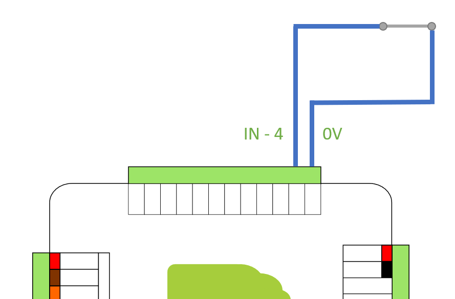
To use the VOLO fire alarm integration you will need to use General Purpose Input 4 (IN-4) and a 0V pin (there is one adjacent to the IN-4 pin).
We require a voltage free contact (from the fire alarm) to connect or disconnect these two pins (see images below).
info
We sometimes use a variety of terms when describing the state of the fire alarm input (IN-4).
Closed - means that IN-4 is connected to 0V
Low - also means that IN-4 is connected to 0V and so the voltage on that pin is pulled LOW
info
We sometimes use a variety of terms when describing the state of the fire alarm input (IN-4).
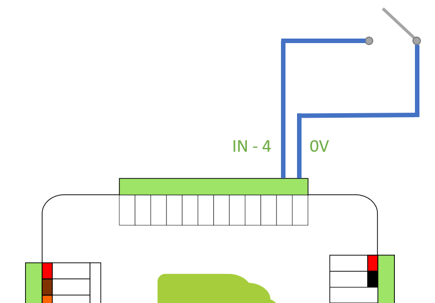
Open - means that IN-4 is NOT connected to 0V
High - also means that IN-4 is NOT connected to 0V and so the voltage on that pin is HIGH
The VOLO controller is expecting one state (open or closed) to indicate a fire has been detected and the opposite state to indicate that the environment is safe - either no fire has been detected or it has been cleared.
We recommend connecting the fire alarm input to the controller before configuring the software.
Software Configuration
The fire alarm integration setting can be configured at the Customer, Site or Controller level. You should select the most appropriate place to configure this based on the specific details of your installation(s).
For example, if every VOLO installation for a specific customer will have a fire alarm integration, and it will always use the same input signal (i.e. the same fire alarm panel/system is used), then you could make this configuration once, at the customer level.
If your customer has less consistent needs, then you can configure site by site, or controller by controller.
Configuration Options
In the screenshot below we are using the Customer settings.
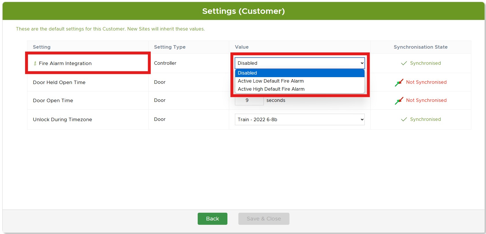
You can see that there are 3 configuration options for the fire alarm integration:
- Disabled
- Active Low Default Fire Alarm
- Active High Default Fire Alarm
note
It can be helpful to interpret the active settings as "Integration is Active, using a Fire Alarm with a Default input of High" (or low).
So, "Active Low Default Fire Alarm" will interpret a 'Low' (IN-4 connected to 0V) as safe/no fire and 'High' (IN-4 not connected to 0V) as a fire is detected.
These should be interpreted as follows:
| Configuration Option | IN-4 State | Outcome |
|---|---|---|
| Disabled | Open/High (not connected to 0V) | "General Input 4 Low" Event raised, no other action |
| Disabled | Closed/Low (connected to 0V) | "General Input 4 High" Event raised, no other action |
| Active Low Default Fire Alarm | Open/High (not connected to 0V) | Fire alarm is active (fire detected) - doors unlocked and events raised |
| Active Low Default Fire Alarm | Closed/Low (connected to 0V) | Fire alarm is inactive (no fire detected) - when confirmed in the volo website, doors locked and events raised |
| Active High Default Fire Alarm | Open/High (not connected to 0V) | Fire alarm is inactive (no fire detected) - when confirmed in the volo website, doors locked and events raised |
| Active High Default Fire Alarm | Closed/Low (connected to 0V) | Fire alarm is active (fire detected) - doors unlocked and events raised |
Operation
Activating the Fire Alarm
When an ACTIVE fire alarm input is detected, the VOLO master controller will immediately unlock the doors it controls and send a message to all connected Expansion controllers to do the same.
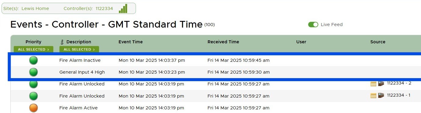
When this occurs, a number of events will be generated:
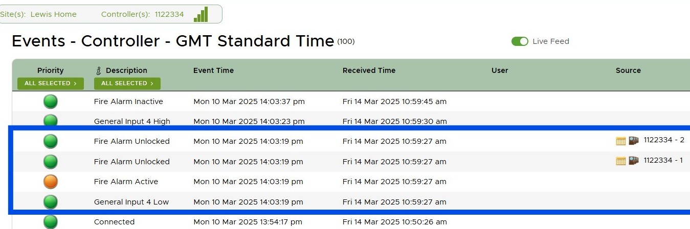
Here you can see the standard event indicating that the General Input has changed state (in this case, it has changed to LOW). Following this, you can see that the Fire Alarm Active event is raised, followed by an event for each door that has unlocked in response to the fire alarm "Fire Alarm Unlocked".
Resetting the Fire Alarm
When the building has been confirmed as safe, the following steps should be taken to reset the fire alarm feature in VOLO:
- Reset the fire alarm input (this should occur when the fire alarm panel is reset)
- Log in to the VOLO software
- As you navigate around the website, you should see a pop-up on every page indicating that a fire alarm is active
- Click the 'Clear Alarm' button on this pop-up
- This will send a command to the master controller confirming that the building is safe and that doors can be locked
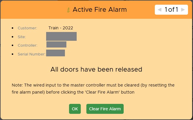
caution
You must clear the wired input to the master controller first (by resetting the fire alarm panel).
If you attempt to clear the fire alarm through the website while the local input is still active, then the VOLO controller will immediately go into a fire alarm state again - generating additional events and unlocking the doors.
Once the fire alarm has been cleared, you will see the following events: